说明:
- 本文档由DuRuofu撰写,由DuRuofu负责解释及执行。
修订历史:
| 文档名称 | 版本 | 作者 | 时间 | 备注 |
|---|---|---|---|---|
| ESP-IDF自定义组件 | v1.0.0 | DuRuofu | 2024-02-18 | 首次建立 |
ESP-IDF自定义组件
一 、自定义组件介绍:
之前在ESP32工程结构及构建里提到esp-idf项目的结构如下:
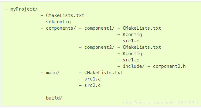
其中components文件夹就是我们自定义的组件。ESP-IDF组件机制就是代码模块化的一种体现,将特定功能的代码封装为一个个组件并对外暴露接口,增强代码的可复用性,提高代码维护效率。
二 、自定义组件示例:
下面我们基于ESP-IDF项目配置中编写的blink_menuconfig工程来实现一个自定义的控制闪烁的组件。
复制工程,重命名为blink_component
使用命令:idf.py -C components create-component led_blink
目录下多出一个叫blink_component的组件
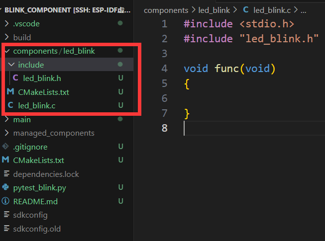
组件的代码结构如下:
- led_blink/ - CMakeLists.txt
			 - Kconfig
			 - led_blink.c
			 - include/
- led_blink.h将点灯的函数定义裁剪到 led_blink.c
c
#include <stdio.h>
	#include "led_blink.h"
#include "freertos/FreeRTOS.h"
#include "freertos/task.h"
#include "driver/gpio.h"
#include "esp_log.h"
#include "led_strip.h"
#include "sdkconfig.h"


static const char *TAG = "led_blink";

/* Use project configuration menu (idf.py menuconfig) to choose the GPIO to blink,
   or you can edit the following line and set a number here.
*/
#define BLINK_GPIO CONFIG_BLINK_GPIO


#ifdef CONFIG_BLINK_LED_RMT

led_strip_handle_t led_strip;

void blink_led(void)
{
    /* If the addressable LED is enabled */
    if (s_led_state) {
        /* Set the LED pixel using RGB from 0 (0%) to 255 (100%) for each color */
        led_strip_set_pixel(led_strip, 0, 16, 16, 16);
        /* Refresh the strip to send data */
        led_strip_refresh(led_strip);
    } else {
        /* Set all LED off to clear all pixels */
        led_strip_clear(led_strip);
    }
}

void configure_led(void)
{
    ESP_LOGI(TAG, "Example configured to blink addressable LED!");
    /* LED strip initialization with the GPIO and pixels number*/
    led_strip_config_t strip_config = {
        .strip_gpio_num = BLINK_GPIO,
        .max_leds = 1, // at least one LED on board
    };
    led_strip_rmt_config_t rmt_config = {
        .resolution_hz = 10 * 1000 * 1000, // 10MHz
    };
    ESP_ERROR_CHECK(led_strip_new_rmt_device(&strip_config, &rmt_config, &led_strip));
    /* Set all LED off to clear all pixels */
    led_strip_clear(led_strip);
}

#elif CONFIG_BLINK_LED_GPIO

void blink_led(int s_led_state)
{
    /* Set the GPIO level according to the state (LOW or HIGH)*/
    gpio_set_level(BLINK_GPIO, s_led_state);
}

void configure_led(void)
{
    ESP_LOGI(TAG, "Example configured to blink GPIO LED!");
    gpio_reset_pin(BLINK_GPIO);
    /* Set the GPIO as a push/pull output */
    gpio_set_direction(BLINK_GPIO, GPIO_MODE_OUTPUT);
}

#endif在头文件声明函数:
c
#ifndef LED_BLINK_H
#define LED_BLINK_H

#ifdef __cplusplus
extern "C" {
#endif

#include <stdint.h>

// Function declarations
void blink_led(int s_led_state);
void configure_led(void);

#ifdef __cplusplus
}
#endif

#endif /* LED_BLINK_H */组件下新建idf_component.yml文件引入组件依赖的led_strip组件
dependencies:
espressif/led_strip: "^2.0.0"新建Kconfig文件,移植组件配置,参考ESP-IDF项目配置
menu "点灯组件配置"
    choice BLINK_LED
        prompt "LED模式"
        default BLINK_LED_GPIO

        config BLINK_LED_GPIO
            bool "GPIO"
        config BLINK_LED_RMT
            bool "RMT - Addressable LED"
    endchoice

    config BLINK_GPIO
        int "LED引脚"
        default 2
        help
            This is an int BLINK_GPIO.

    config BLINK_PERIOD
        int "LED周期"
        default 1000
        help
            This is a int BLINK_GPIO.


endmenu这样就编写好了一个组件。
然后在main组件里引入模块使用即可:
c
#include <stdio.h>
#include "freertos/FreeRTOS.h"
#include "freertos/task.h"
#include "esp_log.h"
#include "led_blink.h"

static const char *TAG = "example";
uint8_t s_led_state = 0;

void app_main(void)
{
    /* Configure the peripheral according to the LED type */
    configure_led();

    while (1) {
        ESP_LOGI(TAG, "Turning the LED %s!", s_led_state == true ? "ON" : "OFF");
        blink_led(s_led_state);
        /* Toggle the LED state */
        s_led_state = !s_led_state;
        vTaskDelay(CONFIG_BLINK_PERIOD / portTICK_PERIOD_MS);
    }
}这样就完成了代码的模块化,关于组件依赖,嵌套还有一些值得注意的地方,不过目前入门阶段不必深究,后续学习过程中会娓娓道来。